Design
See the design breakdown by subcomponent.
Final Assembly:
The Linear Fatigue Tester was designed to load test samples with up to 1000 lbf in tension and compression at 1,000,000 cycles in 24 hours. This is accomplished by a 5 horsepower motor and a con-rod that loads spring attached to a sample. Load amplitude is controlled by an adjustable radius that changes the forced displacement on the springs. The machine can test with any chosen mean stress, including cycling only tension, only compression, or a combination of both.

Motor and Transmission:
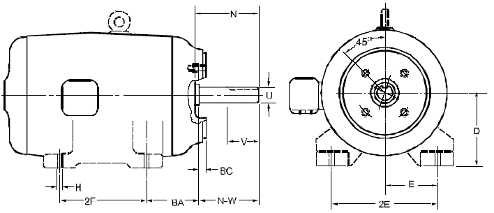
The heart of the Linear Fatigue Tester is the motor. We wanted to have the ability to potentially apply loads as high as 1000 lbs at a minimum rate of 1,000,000 cycles in a day (a little more than 11 hz). Applying high loads at high frequencies requires a powerful motor. Hydraulic and pneumatic motors require pressurized oil or air lines, while combustion engines produce exhaust gasses and are not as smooth. We chose to power our machine with an electric AC motor given that it was the best horsepower/dollar motor we could find. The electric motor also has the benefit of relatively smooth, quiet operation and running off of the most widely available "fuel", electricity. AC motor speed controllers are extremely complex and expensive, so we opted to wire a relay in series with our motor for much cheaper on/off control.
Our decision to implement on/off control meant that our motor could only run at one speed, 3450 rpm (57.5 hz). One can note that it takes a constant amount of work to bring a specimen through one cycle, so fewer cycles happening per second means more work (a higher force exerted over the same distance) can go into each cycle. We optimized our setup to have the highest possible max applicable load, which meant running at the slowest acceptable speed. Ultimately, we chose to run a 72T driven sprocket with a 15T driving sprocket, corresponding with machine operation at just above our minimum spec.
Our linear fatigue tester exerts high cyclical loads on a test specimen. All of those high cyclical loads are also seen by the machine itself, and while our goal is to produce fatigue failure, it is critical that this failure occurs in the specimen rather than the machine. We calculated the effective Goodman stress acting on our motor ans transmission shafts. Goodman effective stress is a good conservative value to use when estimating fatigue life. Our motor supplier did not provide info on the grade of steel used in the output shaft, however our calculations showed that even the weakest steels could handle the loads in our machine with a load factor of 7.6. The higher torques at the transmission shaft combined with the high specimen loads going into the shaft with cantilever support meant that we had to use a hardened 4140 shaft in order to ensure it would not crack. The same calculations for finding the load on the transmission shaft were also used to find the load on the transmission bearings and ensure that they too would not fail.

Adjustable Radius:
The adjustable radius design sees very high stresses in the base of the pin on the slider. The two variables we can adjust are the thickness or shape of the pin and the location of the applied force. Because the shape we are analyzing is very short and thick, we cannot use beam theory. Thus we must iterate using FEA analysis. We designed this part to a conservative safety factor of 2 for the endurance strength of 4130 steel. We chose 4130 steel for this part because it has high fracture toughness and fatigue properties, while still being relatively cheap. We also want to choose material that we can weld easily, because there are two welded parts on this assembly. We want to maintain clearance between the conrod and the pin allowing for space for possible deformation, so it is not optimal to place the conrod right at the base of the pin. We were able to achieve the desired safety factor with a 5/16" offset, which we deemed acceptable. The deformation and stresses in the remaining cylinder and shaft are very small relative to the pin, so these parts were excluded from the final FEA analysis to allow more detail in the more critical pin.
The next important design parameter is designing the slider interface. It must be highly toleranced on the contact surface between the adjustment tube and the slider because this will be a sliding wear surface, and the conrod force could impact loads if they are allowed to develop separation. Thus, these parts will designed to be waterjet cut and then CNC milled to finish. We believe that with machine shop capabilities available and the experience we have machining on our team we can achieve a .005" tolerance on this part. This should be sufficiently tight to prevent impacts.
Con-rod and Linear Rail:
The con-rod and linear rail subassembly is responsible for converting the rotary motion of the motor to linear motion that acts on the springs. The con- rod was designed to minimize its length to mitigate buckling under max compressive loads. To provide 0.25" minimum clearance between moving part the minimum con- rod length was 7" bearing center to bearing center. Using a pin- pin boundary condition for Euler buckling we get a factor of safety of 73.3 on load.
The con-rod attachment to the cylinder body is a double shear pinned connection. Hertzian contact stresses determined the pin hole size such that the hole would not ovalize or fatigue. The con-rod bearings were sized to be the smallest bearings that were rated over 1100 lbf in dynamic loading.
Linear rail carriages are attached to the cylinder body by small blocks that are welded to the cylinder body. Two carriages were necessary because 1 carriage would not be able able to react the full pitch moment applied to it. By using 2 carriages the moment from the con-rod is reacted by load sharing between the 2 carriages.
Cylinder Body:
The cylinder body applies load to the springs. Assembly and maintenance is made possible using an open half cylinder. The main load constraints on the cylinder body are the large compressive loads that could potentially buckle the body. This is potentially high risk due to the cylinder being open on one side. A SolidWorks buckling FEA was run to ensure that the structure would not buckling in this situation. This was performed by fixing the fixed specimen side of the cylinder and applying a 1000 lbf compressive load on the con-rod side of the cylinder . Because the full load was used in the simulation, the resulting load factor is the buckling factor of safety.
Specimen Fixture:
The purpose of the specimen fixture is to mount the specimen and collect real-time load data that can be fed into the control loop. It is rigidly attached to the machine base and does not move. Because of this, weight is much less of a concern than other parts in the machine. The main objectives for this assembly are resistance to fatigue, ability to accurately and reliably measure loads, and low cost and ease-of-assembly.
Steel is the obvious choice to meet the first requirement as it has an endurance limit. Stresses under the limit do not damage the part. For 4130 steel, the endurance limit is 49 ksi. All stresses will be kept below this limit. Secondly, strain gauges are an easy and capable method for getting load data, and one we have considerable experience in. Strain gauges work best when there is a thin section to deform relatively highly compared to the rest of the part. Thin sections under compression carry a risk of buckling, so we will need to ensure that this does not happen. We will be using a full bridge setup. This allows us to negate bending and heating effects, although both are unlikely to occur. It also allows us to amplify the output, meaning we can get the same resolution with a stiffer loadcell.